
WARNING: The following article is based on the code of version 2020.3.4 of Unity and version 10.4 of the Universal Render Pipeline (May 16th, 2021). Although the code has changed a lot since then, the main concepts and the architecture of the engine may still be the same so the text below should be useful for you anyway.
Introduction
The problem
How the light rendering system of the URP works
The solution: Light texture caching
Possible improvements
Limitations
Demo
The implementation of this feature is available in my fork of the URP code repository.
You can discuss about this feature in the Unity forums.
Introduction
The Universal Render Pipeline (URP) provided by Unity offers two “scriptable renderers”, one intended for general 3D rendering and another specialized in rendering 2D environments (3D geometry orthogonally projected to the screen): the 2D Renderer. One of the main advantages of using the 2D Renderer, apart from code optimizations, is that it comes with its own lighting system, which was one of the main reasons for me to choose it for developing Jailbroken. This system works with 2D lights that affect polygons in a different way than 3D lights do, there is no vector arithmetic among light direction and triangle normal occurring per pixel; instead, as we will see in the following sections, lights are drawn to a screen-size texture (“light texture”), masked by another texture previously filled with shadowed areas; then the “light texture” is used as input when drawing geometry like sprites, affecting the output color. In order to project shadows, the system gives us shadow caster components that define 2D polygonal shapes. As in the real world, shadow geometry is not drawn as “semi transparent black” figures over affected sprites, instead they just remove the presence of light.
This article describes how to implement an optimization of the 2D lighting system that may drastically reduce the workload of the GPU in scenarios where a lot of static lights and shadows appear in camera. The technique is similar to the baked lightmaps used in 3D scenarios and requires that the developer does some previous work in the editor.
The problem
Basically, it is an obvious scalability problem: the more lights you add to the scene the poorer the overall performance is (or the more the CPU and GPU are used per frame). Normally, taking into account the power of nowadays machines, this performance loss goes unnoticed, even more when most of the 2D games out there do not require using a big amount of “actual” lights or, especially, when most of them do not use dynamic lights or shadows at all.
I realized this may become a problem for my game when it was tested on a computer with a very low-specs GPU (a GeForce GT 1030). For a small scenario of the game, with 50 lights and 1 shadow caster (60 triangles) for the tilemap, FPS were dropping below 30 sometimes. That’s not acceptable. Working on more complex scenarios in that computer was almost impossible, as FPS went below 5 in the Unity editor. Later I discovered that the problem had to do with a bug in the drivers. Anyway, after updating them and fixing the issue, FPS were always oscillating among 30 and 60 (in editor) and I thought it should be better.
I had already implemented several optimizations of the 2D Renderer and discovered some good practices, but they were not enough. After many tests, it was clear that the bottleneck was the amount of draw calls so I worked in that direction. I tried using instancing when drawing the lights and shadows, but I found that the lighting technique was not conceptually compatible with instancing. After some other failed research, the idea of caching the lights came to my mind.
How the light rendering system of the URP works
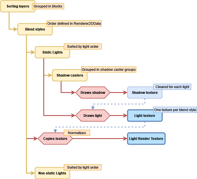
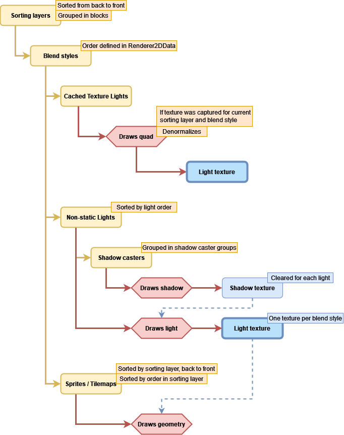
In order to understand both the problem and the solution, it is necessary to know how the lighting system works internally. I’m not going too deep as it is not necessary for any person to get the idea. The following diagram serves as a good first approach to how the system executes its rendering tasks: what data it uses, how it sorts the geometry, in which order it renders the different elements, etc. I have omitted many details and oversimplified some steps so you can focus on the important things.
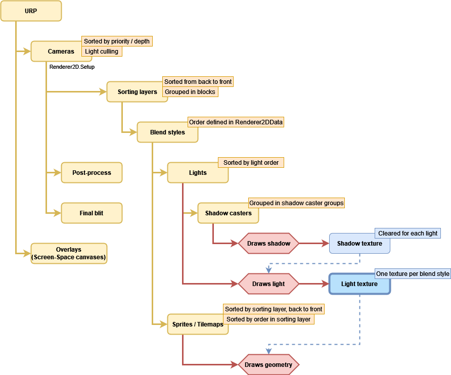
- The URP takes all active Camera objects and sorts them by the value of their priority or depth property, the lowest value first.
- For each camera, it discards all active Light2Ds whose shape is not going to appear in camera and sorts them by their light order property, the lowest value first. Then it tells the Renderer2D to draw all the geometry contained in the frustum of the camera using the lights that were not discarded, apply the post-process effects and copy the result to the backbuffer.
The geometry drawing process is formed by a chain of nested loops that classify and sort the lights and the sprites / tilemaps that are affected by such lights.- First it takes the existing sorting layers defined in the editor (available through SortingLayer.layers), sorts them from back to front, and starts iterating through the list. The way it goes through the list is important as it will not necessarily step on every item; instead it calculates ranges so if, for the current light set, all the lights that are targeting a sorting layer and also the 3 next contiguous sorting layers in the list, it will identify that as a block, so it renders everything only once as if it was only one sorting layer. I explain it in more detail here.
- Once we have the current sorting layer, it takes the existing blend styles (Additive, Multiply, etc.) defined in the Renderer2DData asset and selects them one by one in the same order they appear there, only if there is any light that uses that blend style.
- It takes one of the screen-sized “light textures” created before rendering (one per blend style) corresponding to the current blend style.
- For each light that targets the sorting layer and uses the blend style:
- If the shadow intensity property of the Light2D is greater than zero, it renders all the ShadowCaster2Ds of the scene that are affected by the current sorting layer (I’m omitting the existence of ShadowCaster2DGroup). It creates or clears a screen-sized “shadow texture” and a Stencil buffer (which is used to group shadow casters as if they were one mesh). For each shadow caster:
- Draws the mesh of the shadow caster with a special material that uses a shader with 2 passes, one that moves the vertices of the mesh away from the position of the light (creating the illusion of projected shadows) and another that just draws the mesh (they pass the Stencil test if they belong to a group different from what was drawn before in each pixel). In both cases, they write a color on the “shadow texture” using additive blending. Each channel of the color (RGB) has a special meaning that I will explain later. So far, it has drawn the mesh twice.
- If the Use Renderer Silhouette property of the shadow caster is enabled, it renders the mesh of the sprite using a material that depends on whether the Selft Shadows property is enabled or not.
- If the Use Renderer Silhouette property of the shadow caster is not enabled and the Selft Shadows property is disabled, it renders the mesh of the shadow caster using a material intended to “remove” the shadow in the area occupied by the mesh.
- In the worst case, it renders the same mesh 3 times on the “shadow texture” for each shadow caster in the scene and every light.
- Then it renders the light. The mesh of the light depends on the type (Point, Freeform, Sprite…) and its material depends also on the blend style and the volume opacity, among other things. The fragment shader receives the “shadow texture” generated in the previous step which serves as a mask that tells it which pixel belongs to a shadowed area. The result is blended into the “light texture” being used for the current blend style.
- If the shadow intensity property of the Light2D is greater than zero, it renders all the ShadowCaster2Ds of the scene that are affected by the current sorting layer (I’m omitting the existence of ShadowCaster2DGroup). It creates or clears a screen-sized “shadow texture” and a Stencil buffer (which is used to group shadow casters as if they were one mesh). For each shadow caster:
- Sprites and tilemaps that are affected by the current sorting layer are sorted by their Order in Layer property, the lowest first.
- For each sprite or tilemap affected by the current sorting layer, all the “light textures” (one per blend style) generated in the previous steps are sent to the fragment shader so it blends them to produce the final color.
- It renders all the lights that use the current sorting layer and the blend style, and whose volume opacity is greater than zero (they are drawn atop of the sprites).
- It renders all the geometry that has to appear over everything else and is not affected by lights, like the UI elements that belong to a canvas with Screen Space – Overlay render mode.
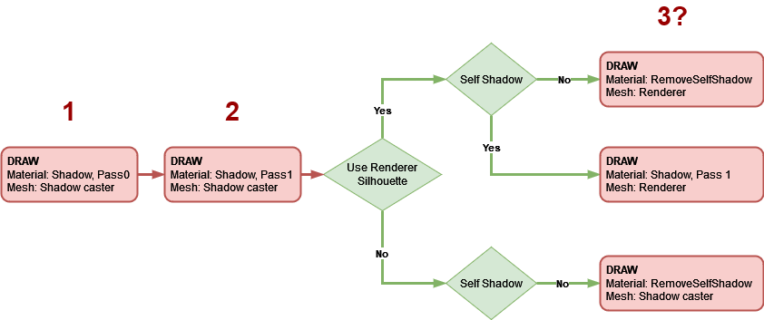
I want to focus on the last part, the renderization of the light and the shadows casted by it. This diagram shows the drawing steps for a ShadowCaster2D in a more visual way:
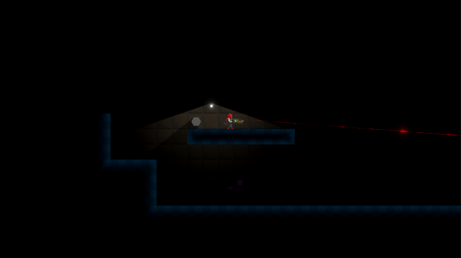
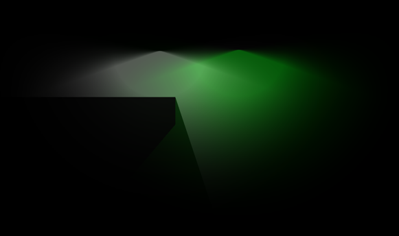
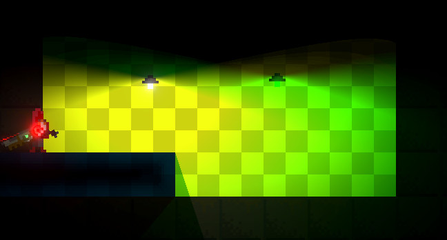
Let’s use the following scene as an example of how the illumination is built:
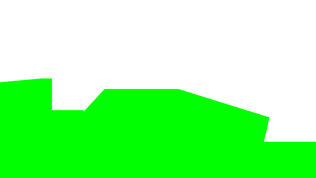
1. First, it uses the mesh of the shadow caster (which is different from the shape of the sprite) and executes the first pass of the “shadow” material to write to the “shadow texture” and to the Stencil buffer. The color it writes to the “shadow texture” is always orange, using additive blending. If the index of the group to which the shadow caster belongs (I’m not going to explain where the index comes from) has been written previously to the Stencil buffer, then the color is not written. This makes sure that overlapping geometry (after it has been deformed by the vertex shader to fake how meshes casts shadows) will not add color to itself; the color of all the written pixels will be the same.

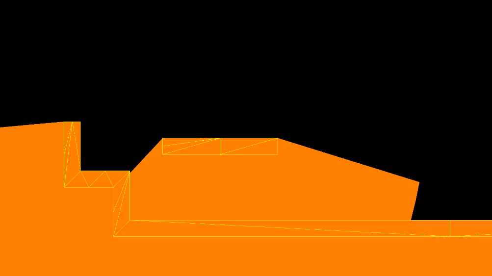
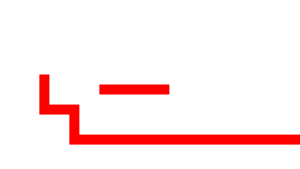
Here you can see the result of the Stencil test (gree passed, red failed):
2. Then it repeats the operation but using the second pass of the material; this pass always writes orange color. It uses the same blending and stencil testing parameters. Honestly, I haven’t been able to figure out the purpose of this executing step right after the other pass, as it never passes the Stencil test, it seems to be a waste of GPU resources; maybe it was included as part of a future feature. If there is any Unity employee reading this, I would love to know the explanation (I’m going to remove it from my fork).
3. The last step makes the mesh either look shadowed or not. There are 3 possibilities:
- If the shadow caster uses the silhouette of the renderer attached to the same object (SpriteRenderer, TilemapRenderer…) and it shades itself, the system uses the second pass of the previous “shadow” material to draw the mesh of the renderer (which may differ a lot from the mesh of the shadow caster). The result of this is adding some new orange pixels that were not written by the mesh of the shadow caster. Since the shape of the shadow casters of a tilemap often coincides with the shape of the mesh of the tilemap, I recommend not to activate the Use Renderer Silhouette property of the ShadowCaster2Ds attached to it.
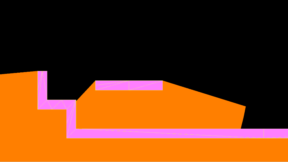
- If it uses the silhouette of the renderer and it does not shade itself, the “remove self shadow” material is used for drawing the mesh of the renderer. This material writes RGB(0, 0, 1, 0) blue color using additive blending if the shadow caster group index stored in the Stencil buffer is the same.
- If it does not use the silhouette of the renderer and it does not shade itself, the system uses the same material described in the previous paragraph to draw the mesh of the shadow caster.
In this picture, you can see how the blue color is added to the orange color, forming light magenta.
The meaning of the colors in the “shadow” texture (called “_ShadowTex” internally) is:
- R: 1 means the pixel is shadowed (totally or partially); 0 means it is not at all.
- G: 0.5 means the pixel is shadowed by the current shadow caster only; 1 means it has been shadowed by more than one.
- B: 1 means the pixel is not shadowed by the current shadow caster, even if R equals 1, although it may be shadowed by another shadow caster; 0 means nothing.
So, in the end, the only 5 possible colors that appear in the “shadow texture” are:
- RGB(1, 0.5, 0) orange: Pixel shadowed only once.
- RGB(1, 1, 0) yellow: Pixel shadowed more than once.
- RGB(1, 0.5, 1) light magenta: Pixel shadowed only once, self shadow removed.
- RGB(1, 1, 1) white: Pixel shadowed more than once, self shadow removed but shadowed by other shadow caster.
- RGB(0, 0, 0) black: Pixel not shadowed.
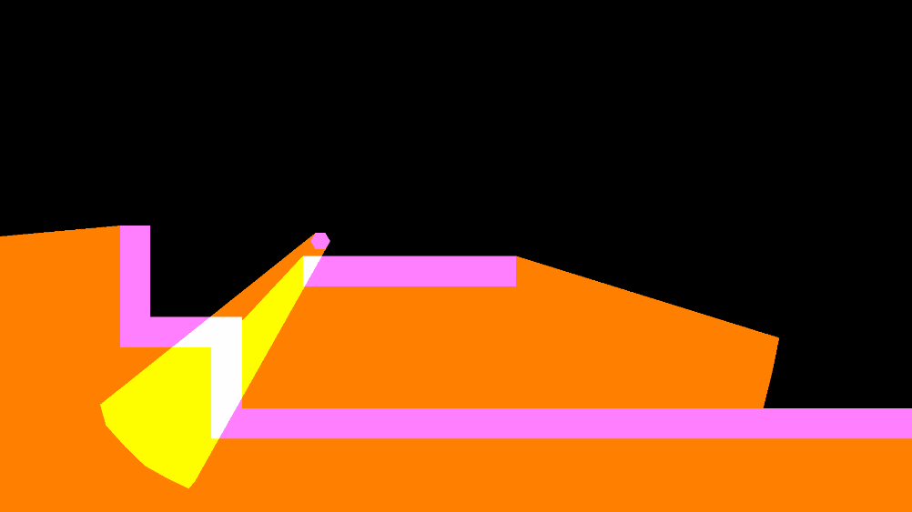
As an example with all the colors:
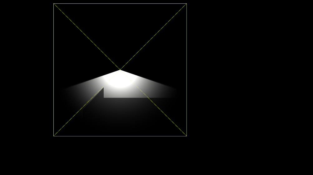
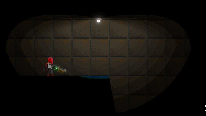
Once all shadow casters affected by the light have been rendered, the “shadow texture” is used as input for the shader of the light and the geometry of the light is finally drawn on the “light texture” along with the other lights of the same sorting layer and blend style. In this example, it is a white point light that draws 12 triangles using alpha blending, with the stencil test disabled.
After all the lights that share targeted sorting layers and blend style have been added to the texture (remember, there is a light texture per blend style), it is used as input in the shaders of the sprites and tilemaps.
By the way, thanks again Baldur Karlsson for creating RenderDoc, which allowed me to capture the previous pictures, and without which all the reverse engineering I did to create this feature would not have been possible.
The solution: Light texture caching
As we have seen, the amount of geometry to draw increases quickly as we add new lights that project shadows (shadow intensity > 0), due to every light requires rendering all the shadow casters and every shadow caster draws its mesh either 2 or 3 times. And I’ve not mentioned yet the cost, in terms of CPU consumption, of preparing the data to be sent to the GPU. If lights are moving all the time, their shadows must be re-calculated on every frame, that’s obvious; but why to calculate shadows again and again for lights that we know will never move?
Here is where the caching / baking feature comes into play! This is the main idea:
Capturing light textures
As with other optimization strategies, like 3D lightmaps, we are going to perform all the calculations in advance and store the results in data assets that will feed the renderer later. This process must be done in the Unity editor every time we change any of the static lights or any of the shadow casters in a game level.
We know that a “light texture” is filled for each combination of sorting layer block (remember what I explained) and blend style, and we need a way to get those textures out of the 2D Renderer in order to store them on disk. The method I chose consists in using the Renderer2DData asset as a communication channel between the game and the 2D Renderer, as it is accessible by both. This is what I added to it:
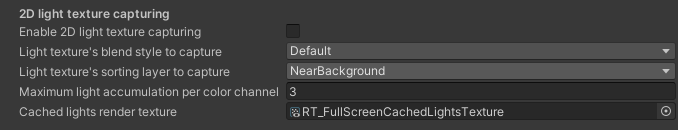
A flag that enables / disables the capturing process; the sorting layer (the lower bound of the range) and the blend style of the “light texture” to capture; a floating point number (that I will explain later), and a reference to a RenderTexture (RT) asset.
The purpose of the RT is to copy a “light texture” onto it every time the 2D Renderer renders a frame. This implies that it is necessary to execute the game level to fill the RT. Once the RT contains the copy we can “take the photo” (also in runtime), which consists in creating a new asset (if it does not exist yet) in the same folder that contains the scene asset of the game level, where to store the following data for each captured texture:
- A copy of the RT as a PNG file.
- Object-to-world matrix of the quad that will be used to draw the captured texture.
- The sorting layer of the captured texture.
- The blend style of the captured texture.
- The maximum light accumulation per color channel applied to the captured texture.
Every time a “light texture” is captured, another item (I defined the class CachedLightTextureData) must be added to the asset. All the data is copied from the Renderer2DData asset at the moment of the capture, but the matrix. The matrix contains the world position of the camera, the world rotation of the camera and the size of the viewport of the camera in world units, as the scale.
If we reuse a part the first diagram, the lighting system would look like this for now:
Note: I had to add 2 new properties to the Light2DCullResult class and split the visible lights into static and non-static, based on whether every GameObject is static or not.
Texture formats
The format of the RT is the same as the format of the “light render-textures”, B10G11R11_UFLOAT_PACK32, which is formed by a 11-bits Red channel, a 11-bits Green channel and a 10-bits Blue channel (32 bits per texel) which can only store unsigned floating point numbers. The reason why I decided to store the copies of the RT as PNG files is disk space. The RT occupies 7.9 MB in memory (the asset only contains metadata, it does not store pixels on disk) while a PNG file of the same size requires between 200 and 400 KB on disk (loss-less compression) and 5.9 MB on memory using the format RGB8 UNorm, formed by 3 channels of 8-bits that store unsigned normalized values (from 0.0 to 1.0), in linear color-space. Unity lets us compress the textures in memory even more to reduce their size up to 30 KB, although lights would look awful. BC7 format (high quality compression) is enough, the texture occupies around 2 MB and the loss of quality is barely noticeable (mostly some banding effects).
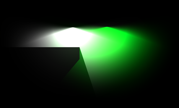
Maximum light accumulation per color channel: Texture normalization
When copying the RT to the PNG, a format conversion must occur from R11G11B10 (unsigned) to R8G8B8 (unsigned normalized). Since the former is not normalized, it can store any unsigned float that could be represented with 11 or 10 bits, whereas the latter, normalized, can only store values from 0 to 1. If two or more lights overlap, the sum of both may produce values greater than 1 in the “light texture”. How to make a value greater than 1 fit into the normalized range [0, 1]? This is not something that happens automatically when copying pixels from one texture to the other; in fact, it is not possible to copy them directly as Graphics.CopyTexture requires both to use the same format, and Texture2D.ReadPixels clamps the values of the RT between 0 and 1 (documentation does not specify that, but I guess Unity calls the glReadPixels function underneath whose documentation makes it clear).
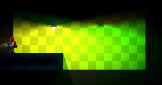
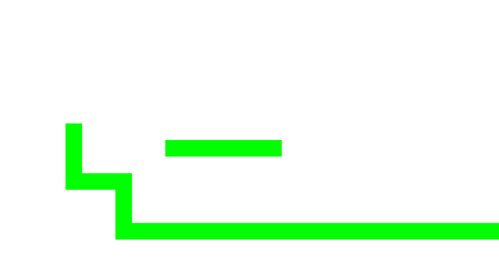
The picture above shows how the white and the green lights interlace each other in the overlapping area, when using the original “light texture”. The picture below shows what happens when the “light texture” is copied to a texture with a normalized format. You can see how the white light prevails over the green light (I chose a yellow background because the effect was more evident with that color). The sum of both light colors is producing values that are greater than 1.0 in the “light texture” and those values are clamped in the destination, so White + Green = (1.0, 2.0, 1.0) → (1.0, 1.0, 1.0) .
We need to manually normalize the color channels before we copy the RT, and normalization requires reference numbers. Both texture formats are unsigned, so the lower value of reference is zero. The number we need to figure out then is the maximum value a color channel in the “light texture” may store. If we know that the maximum amount of static lights that are overlapping at any point of the scene is 2, and that the intensity of the lights is, at most, 1.0, then we could set the maximum value as 2 x 1.0 = 2.0 when capturing “light textures” for that scene. That should be the number we would set in the property of the Renderer2DData. What would this imply when copying a “light texture” onto the RT?
The process is simple. Right after the static lights have been rendered to the “light texture”, before the 2D Renderer processes the non-static lights, a quad as big as the viewport of the camera is drawn onto the RT using a special material / shader whose only purpose is to divide every color by the maximum value. If we continue with the previous example, the normalized version of the color (2.0f, 1.0f, 1.5) would be (1.0, 0.5, 0.75) in the RT. Normalization has an undesired side-effect: we lose precision (the separation between consecutive values is greater) and that may be visible on the screen in the form of banding effects. The higher the maximum value is, the lower the precision, so if you are sure that there are no overlapping static lights, keep it to 1.0.
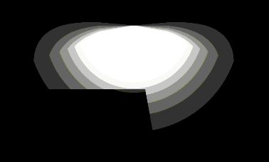
The pictures below show the banding effect with a maximum value of 50. Now I think that it does not look that bad, if you want color-quantized lights for your game…
Drawing cached light textures
The second step in the light texture caching process consists in reading and applying the data collected in the first step. When a game level is loaded, before the scene is visible, all the cached light textures must be sent to the 2D Renderer. As I explained, the way to connect the game and the URP, in order to keep both worlds decoupled, is to use the Renderer2DData asset as intermediary.
Although it does not appear in the Inspector window, the Renderer2DData asset has a property, intended to be filled in at runtime, which stores a list of cached light textures (remember the data structure I defined). The same list we saved in the previous step is what has to be copied there.
The 2D Renderer is all the time processing the cached light textures from the Renderer2DData. If there is no data, static lights will be rendered as usual; if the list contains items, no static light will be rendered. Instead, the cached light textures will be copied to the current “light texture”, before the non-static lights are rendered and added on top.
For each cached light texture, the 2D Renderer checks if its sorting layer and its blend style match the combination that is being processed and, in that case, it draws a 1×1 quad (in Unity world units) that is transformed by the cached world matrix. The quad is translated to the world position of the camera when the texture was captured, and is scaled so it fills the size of the viewport at that moment.
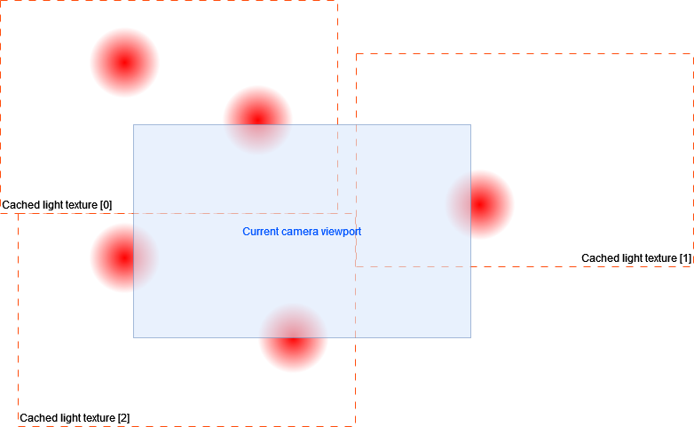
The quad uses a special material that draws a texture (the cached light texture) and (very important) denormalizes the colors before they overwrite the part of the “light texture” covered by the quad. This means that all the colors will be multiplied by the Maximum light accumulation per color channel value we applied in the first step, and which was also stored along with the cached light texture when it was captured.
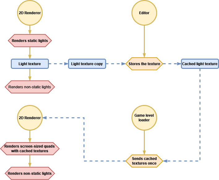
This is how the lighting system looks like now:
That’s it! No more computation time wasted on static lights. Now you need an editor tool that helps you automate everything. I’m working on mine right now, maybe I will show it soon.
Please follow me to stay tuned and share this post with other devs that may find it useful.
Possible improvements
A light texture per light
Instead of drawing screen-sized quads, it may be possible to draw smaller quads that occupy the space determined by the radius of the lights. Some pros and cons come to my mind:
Pros:
- Lights can be enabled / disabled independently.
- Lights are culled by the camera so their quads would not be rendered.
- Smaller textures.
- Lights could change their intensity and color in runtime independently.
- Lights would use quads instead of special meshes that depend on type.
- It would only be necessary to update the texture of one light, when it changes.
Cons:
- A draw call per light, drawing N triangles each.
- For each light, the light texture and the transformation matrix would have to be set.
- High number of lights would have a very high cost, in relative terms.
- More assets.
Generate light textures on-the-fly
Instead of caching the textures manually, in the editor, I think it could be possible to do it when game levels are loaded. It would require to mark where to “take the photos” or tell the system where the spatial limits of the level are, so it would still be necessary to do some work in editor. Another problem that arises is to determine when to capture the textures, since you need to do it when all static lights are ready and the camera is available.
Capturing portions of the screen
Maybe we can just center the camera at some point and choose the width and height of the rectangle we want to capture, instead of storing the entire screen. This would reduce both the size of the textures and the amount of pixels to draw on the “light texture” as quads would adapt to the size of the texture.
Limitations
An important limitation of this technique is that we cannot use moving shadow casters as they would not be affected by static lights (the “light texture” is fixed). It depends on the scenario, of course, maybe you can use it in such a way that the player does not realize about the “visual dissonance”.
Demo
[This section was added afterwards, the 4th of September, 2023]
I implemented an editor tool that makes the light texture capturing process easy and fast. First, you have to know what parts of the scene are affected by static lights, then you put “capture points” in the scene, manually, while the game is not running. A capture point represents a light texture and all the data related to it. Visually, they are a position and a rectangle whose size matches the orthographic size of the game camera. Once all capture points are set, you execute the game level. At runtime, you just press the Capture button and all the light textures are cached, according to your setup. Internally, it moves a special camera to each capture point, waits until the renderer copies the current light texture to the RenderTexture and stores the copy on disk, referenced by the cached light textures asset.
One of the coolest things of this tool is that it allows you to preview the cached light textures and where are they going to be rendered during the light rendering process.
![Read more about the article Animation editor QoL improvements [Repost]](https://jailbrokengame.com/wp-content/uploads/2023/05/AnimationEventSelection-300x81.png)
![Read more about the article Target sorting layers as assets [Repost]](https://jailbrokengame.com/wp-content/uploads/2023/05/Lightinspector-210x300.png)
Hi there. I am really impressed by solutions regarding improvements in unity. It`s a pity there isn`t as much activity as there should have been. I am looking into your project and it gives me a lot of inspiration. Keep it up man, everything is possible!